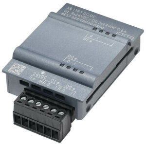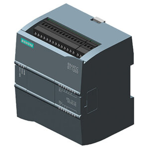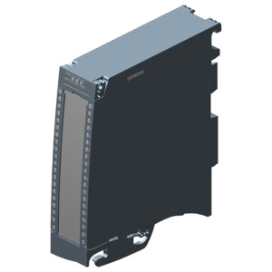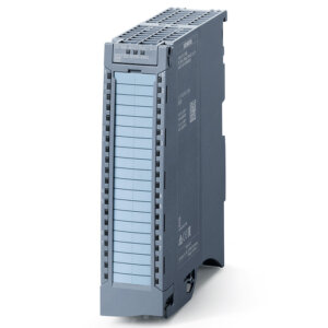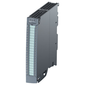
6ES7522-5HF00-0AB0 SM 522 DQ 8x230VAC/5A ST (Relay)
7.454.000 ₫
SIMATIC S7-1500, digital output module DQ 8xAC 230V/5A ST; relay; 8 channels in groups of 1; 5 A per group; diagnostics; substitute value: switching cycle counter for integrated relay, the module supports the safety-oriented shutdown of load groups up to SILCL1 according to EN 62061:2005 + A2:2015, and Category 2 / PL c according to EN ISO 13849-1:2015. front connector (screw terminals or push-in) to be ordered separately.
Tải về datasheet (pdf): Tại đây!
6ES7522-5HF00-0AB0 là mô đun mở rộng tín hiệu ngõ ra số cho PLC S7-1500 do hãng SIEMENS phát triển & sản xuất với thương hiệu SIMATIC thuộc họ S7-1500. 6ES7522-5HF00-0AB0 được MESIDAS GROUP phát triển và phân phối rộng rãi trên thị trường Việt Nam. Nếu quý khách hàng đang có nhu cầu cần tư vấn hay mua 6ES7522-5HF00-0AB0 thì hãy liên hệ MESIDAS GROUP để được hỗ trợ một cách tận tâm, nhanh chóng và hiệu quả nhé.
Bảng tóm tắt thông số kỹ thuật 6ES7522-5HF00-0AB0
SIMATIC S7-1500, digital output module DQ 8xAC 230V/5A ST; relay; 8 channels in groups of 1; 5 A per group; diagnostics; substitute value: switching cycle counter for integrated relay, the module supports the safety-oriented shutdown of load groups up to SILCL1 according to EN 62061:2005 + A2:2015, and Category 2 / PL c according to EN ISO 13849-1:2015. front connector (screw terminals or push-in) to be ordered separately
| Mã sản phẩm | 6ES7522-5HF00-0AB0 |
| Dòng sản phẩm | SIMATIC S7-1500, SM 522 |
| Hãng sản xuất | SIEMENS |
| Số lượng đầu ra số | 8 DQ AC 230V/5A ST (relay) |
| Nguồn cung cấp | 24 V DC (20.4-28.8 V DC) |
| Kích thước (RxCxS) | 35x147x129 mm |
| Trọng lượng | 350 g |
Bảng chi tiết thông số kỹ thuật 6ES7522-5HF00-0AB0
| Article number | 6ES7522-5HF00-0AB0 |
| S7-1500, DQ 8x230VAC/5A ST (Relay) | |
| General information | |
| Product type designation | DQ 8×230 V AC/5 A ST (relay) |
| HW functional status | From FS02 |
| Firmware version | |
| ● FW update possible | Yes |
| Product function | |
| ● I&M data | Yes; I&M0 to I&M3 |
| ● Isochronous mode | No |
| ● Prioritized startup | Yes |
| Engineering with | |
| ● STEP 7 TIA Portal configurable/integrated from version | V12 / V12 |
| ● STEP 7 configurable/integrated from version | V5.5 SP3 / – |
| ● PROFIBUS from GSD version/GSD revision | V1.0 / V5.1 |
| ● PROFINET from GSD version/GSD revision | V2.3 / – |
| Operating mode | |
| ● DQ | Yes |
| ● DQ with energy-saving function | No |
| ● PWM | No |
| ● Oversampling | No |
| ● MSO | Yes |
| ● Integrated operating cycle counter | Yes; FW V2.1.0 or higher |
| Supply voltage | |
| Rated value (DC) | 24 V |
| permissible range, lower limit (DC) | 20.4 V |
| permissible range, upper limit (DC) | 28.8 V |
| Reverse polarity protection | Yes |
| Input current | |
| Current consumption, max. | 80 mA |
| Output voltage | |
| Rated value (AC) | 230 V; 24 V DC to 120 V DC / 24 V AC to 230 V AC |
| Power | |
| Power available from the backplane bus | 0.8 W |
| Power loss | |
| Power loss, typ. | 5 W |
| Digital outputs | |
| Type of digital output | Relays |
| Number of digital outputs | 8 |
| Current-sinking | Yes |
| Current-sourcing | Yes |
| Digital outputs, parameterizable | Yes |
| Short-circuit protection | No |
| ● built-in fuse | |
| Controlling a digital input | Yes; possible |
| Switching capacity of the outputs | |
| ● with resistive load, max. | |
| ● on lamp load, max. | 1 500 W; 10 000 operating cycles |
| ● Low energy/fluorescent lamps with electronic control gear | 10x 58 W (25 000 operating cycles) |
| ● Fluorescent tubes, conventionally compensated | 1x 58 W (25 000 operating cycles) |
| ● Fluorescent tubes, uncompensated | 10x 58 W (25 000 operating cycles) |
| Output voltage | |
| ● for signal “1”, min. | |
| Output current | |
| ● for signal “1” rated value | 5 A |
| ● for signal “1” permissible range, min. | 5 mA; 10 V |
| ● for signal “1” permissible range, max. | 8 A; thermal continuous current |
| ● for signal “0” residual current, max. | 0 A |
| Output delay with resistive load | |
| ● “0” to “1”, max. | |
| ● “1” to “0”, max. | |
| Parallel switching of two outputs | |
| ● for logic links | Yes |
| ● for uprating | No |
| ● for redundant control of a load | Yes |
| Switching frequency | |
| ● with resistive load, max. | 2 Hz |
| ● with inductive load, max. | 0.5 Hz |
| ● on lamp load, max. | 2 Hz |
| Total current of the outputs | |
| ● Current per channel, max. | 8 A; see additional description in the manual |
| ● Current per group, max. | 8 A; see additional description in the manual |
| ● Current per module, max. | 64 A; see additional description in the manual |
| Relay outputs | |
| ● Number of relay outputs | 8 |
| ● Rated supply voltage of relay coil L+ (DC) | 24 V |
| ● Current consumption of relays (coil current of all relays), typ. | 80 mA |
| ● external protection for relay outputs | With miniature circuit breaker with characteristic B for: cos φ 1.0: 600 A cos φ 0.5 … 0.7: 900 A with 8 A Diazed fuse: 1 000 A |
| ● Contact connection (internal) | No |
| ● Number of operating cycles, max. | 4 000 000; see additional description in the manual |
| ● Relay approved acc. to UL 508 | Yes; 250 V AC/5 A g.p.; 120 V AC TV-4 tungsten; A300, R300 |
| Switching capacity of contacts | |
| — with inductive load, max. | see additional description in the manual |
| — with resistive load, max. | see additional description in the manual |
| Cable length | |
| ● shielded, max. | 1 000 m |
| ● unshielded, max. | 600 m |
| Interrupts/diagnostics/status information | |
| Diagnostics function | Yes |
| Substitute values connectable | Yes |
| Alarms | |
| ● Diagnostic alarm | Yes |
| ● Maintenance interrupt | |
| Diagnoses | |
| ● Monitoring the supply voltage | Yes |
| ● Wire-break | No |
| ● Short-circuit | No |
| Diagnostics indication LED | |
| ● RUN LED | Yes; green LED |
| ● ERROR LED | Yes; red LED |
| ● MAINT LED | Yes; Yellow LED |
| ● Monitoring of the supply voltage (PWR-LED) | Yes; green LED |
| ● Channel status display | Yes; green LED |
| ● for channel diagnostics | No |
| ● for module diagnostics | Yes; red LED |
| Potential separation | |
| Potential separation channels | |
| ● between the channels | Yes; Switching of different phases permitted |
| ● between the channels, in groups of | 1 |
| ● between the channels and backplane bus | Yes |
| ● Between the channels and load voltage L+ | Yes |
| ● Between the channels and load voltage L1 | |
| Permissible potential difference | |
| between different circuits | 250 V AC between the channels and the supply voltage L+, 250 V AC between the channels and the backplane bus; 250 V AC between the channels (500 V AC when connecting different phases; basic insulation) |
| Isolation | |
| Isolation tested with | between the channels: 3 100 V DC; between the channels and the backplane bus: 3 100 V DC; between the channels and the supply voltage L+: 3 100 V DC; between the L+ and the backplane bus: 707 V DC (type test) |
| Standards, approvals, certificates | |
| Suitable for safety functions | No |
| Suitable for safety-related tripping of standard modules | Yes; From FS03 |
| Highest safety class achievable for safety-related tripping of standard modules | |
| ● Performance level according to ISO 13849-1 | PL c |
| ● Category according to ISO 13849-1 | Cat. 2 |
| ● SILCL according to IEC 62061 | SILCL 1 |
| Ambient conditions | |
| Ambient temperature during operation | |
| ● horizontal installation, min. | -30 °C; From FS03 |
| ● horizontal installation, max. | 60 °C |
| ● vertical installation, min. | -30 °C; From FS03 |
| ● vertical installation, max. | 40 °C |
| Dimensions | |
| Width | 35 mm |
| Height | 147 mm |
| Depth | 129 mm |
| Weights | |
| Weight, approx. | 350 g |
Nhà phân phối & báo giá 6ES7522-5HF00-0AB0
Nếu quý khách hàng đang có nhu cầu cần tư vấn, báo giá hay mua 6ES7522-5HF00-0AB0 thì hãy liên hệ MESIDAS GROUP để được hỗ trợ một cách tận tâm, nhanh chóng và hiệu quả nhé.
| Trọng lượng | 0,350 kg |
|---|---|
| Kích thước | 3,5 × 14,7 × 12,9 cm |